

Layout Routing
Authors: Michael Cunningham, Joseph Chong, and Dr. Dong S. Ha
Routing example
1. Make sure that you have started layout from schematic window Tools -> Design Synthesis -> Layout XL.
2. Select appropriate layers from LSW, and use rectangles (“r”) or paths (“p”) commands in layout window to route. Connect different layers with vias (“o”). Use higher level metals, wider metal width, and more vias for less resistance. However, don’t overlap different metals too much for less parasitic capacitance.
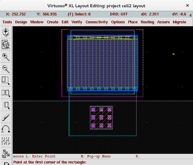
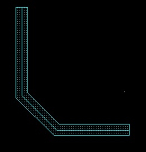
3. An example to route the source of the NMOS to the resistor with rectangle (“r” command) is shown below.
Figure 1. Route NMOS S to resistor with rectangle
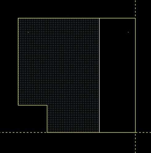
4. An example to route the source of the NMOS to the resistor with path (“p” command) is shown below.
Figure 2. Route NMOS S to resistor with path
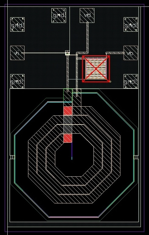
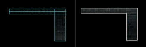
5. If you have connected wrongly, a cross will show on the pin. For example, if a M1 rectangle is drawn overlapping both the resistor pins, they are shorted and the top pin now shows a cross indicating error.
6. Continue the same practice for all the nets. An example of final layout is shown in the figure.
Discussions
1. This just an introductory software usage tutorial for layout, and the final layout above should only be taken as an example created to demonstrate software usage.
2. Different industry has practices that need to be included in the process of layout. E.g., one needs to consider adequate metal width to accommodate current flow in power electronics industry, one needs to consider component matching for precision analog circuits, or one needs to consider electromagnetic travelling effect for high frequency circuits, etc.
3. The foundry has rules that limits minimum and maximum metal width / via sizes / etc. Read foundry document or run DRC check to find out if there’s any violations.
Commands useful in routing
Rectangles and Polygons
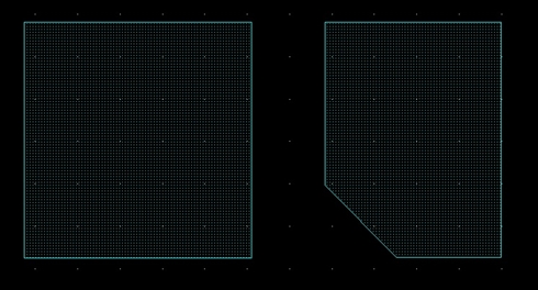
1. To create a rectangle, press "r". We can use these for paths and connections.
2. To create a polygon, press "Shift + p". This is useful for custom shapes (TSMC allows for 45 degree shapes).
Paths
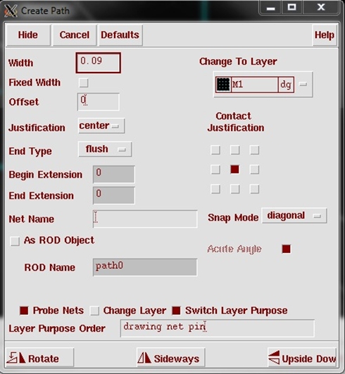
Paths are a special form of rectangles that make routing easier. To create a path, press "p". This creates a path on the selected layer and is very useful for long routes. If you open the path options ("F3") then you can adjust the "Snap Mode" to diagonal for more routing options.
Paths are simple to draw; click a starting point and click anytime you want to change direction. Press "Enter" (or double click) when you are finished.
Chop and Stretch
Chop ("Shift + c") and stretch ("s") allow you to adjust rectangles and patsh by removing a piece (chop) or resizing an edge (stretch).
Merge
Merge ("Shift + m") is useful for joining separate, adjoining paths/rectangles into one.
Gravity
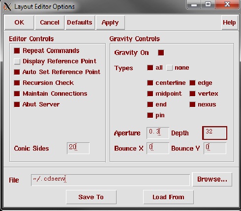
Gravity is very useful for alignment and chopping; it snaps your cursor to corners and midpoints of other shapes. The bindkey "g" toggles gravity on and off. Press "Shift + e" to adjust settings. The aperture sets the distance away from an object that the cursor will snap. Therefore, a large value will snap the cursor at far distances and a small aperture will snap at closer distances. The depth determines how many levels down the snap can access. It ranges from 1 to 32. An aperture of "0.3" and depth of "32" should work fine. Bounce is not active as a default. Changes your .cdsenv file must be made; however, customization is not covered in this tutorial
Ruler
The ruler ("k") is great for measuring specific distances (especially when coupled with gravity). Press "Shift + k" to clear all rulers.

MICS IAP Members


