

Creating Libraries and Schematics in Cadence
In this tutorial, you will learn how to create a library that is attached to TSMC 65nm CMOS library, and the basic steps to create simple a schematic.
Creating a Library
1. Start Cadence under an appropriate directory.
a. For ECE4220 Spring 2017 class, change directory with cdsprj. Then, set system variable with the command Cadence, and use icfb & to start Cadence.
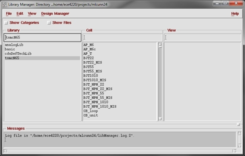
2. Once you have the icfb windows open, select Tools → Library Manager to bring up the Library Manager. Make sure tsmcN65 is in the list of libraries.
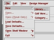
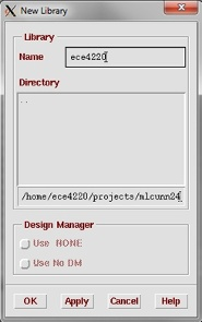
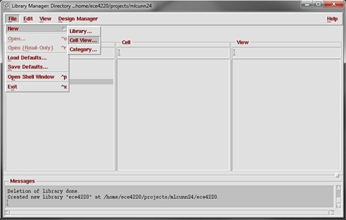
3. In the library manager, create a new library by clicking File → New → Library and name it anything you want, (e.g. ece4220). You can also do this through the icfb window but the steps are slightly different.
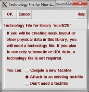
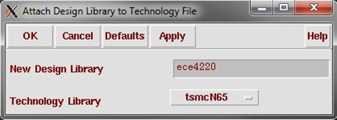
4. In the next window, choose "Attach to an existing techfile". A new window will appear. Select tsmcN65 from the dropdown menu next to "Technology Library".
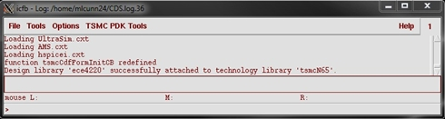
NOTE: If you get an error shown in the icfb window, please see someone for permission to access TSMC 65nm PDK.
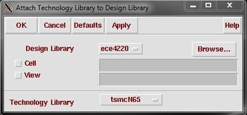
5. If you forgot to attach the technology file, you can do it by going to the icfb window and choosing Tools → Technology File Manager...→ Attach. Select your design library and attach the correct technology file.
Create a Cell View/ Schematic
6. Now, you should be able to see the "ece4220" library (or whatever you named it) on the list of libraries in the Library Manager. Next, select this library so it's highlighted in the Library Manager and click on File → New → Cell View in the menu bar. You can also do this through the icfb window though the steps are slightly different.
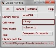
7. A "Create New File" dialog-box will appear. Type in a new Cell Name. Make sure that "View Name" is schematic, "Tool" is select as Composer-Schematic, and "Library Name" is "ece4220" (or whatever you named it). Select OK and a Virtuoso Schematic Editing window will open up.
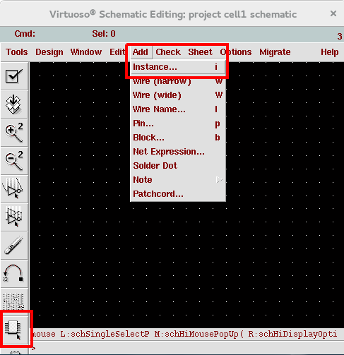
8. First we will want to place the components we need. In the schematic window, create a new instance by using one of the following methods: using the bindkey “i”, selecting the “instance” icon from the left side-bar, or select Add à Instance from the menu.
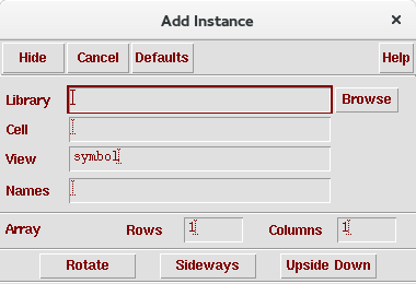
9. The “Add Instance” dialog box will pop up. You may enter the library name and cell name of the component you wish to add, or you may choose it from the list. In this case, let’s click on Browse to choose from the list of components.
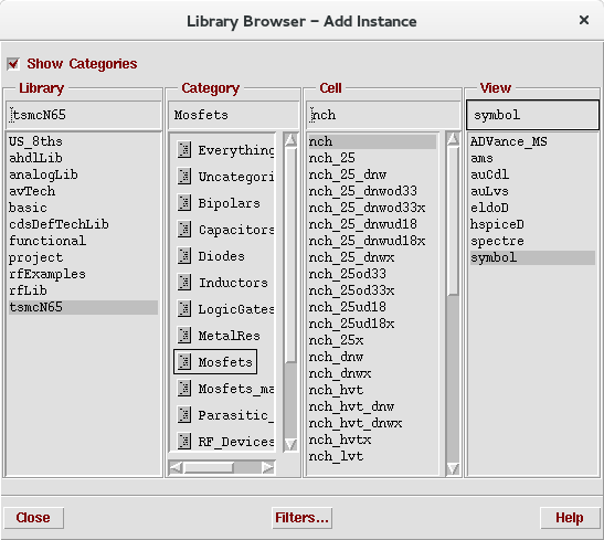
10. The library browser will be opened showing the list of components. Enable “Show Categories” on the top left and click on tsmcN65 library to see all components provided by tsmcN65 PDK. Select Mosfets from the categories, select the nch cell and the symbol view.
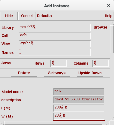
11. The add instance window will be automatically populated with the cell you selected, and you may set its parameter before you insert it to your schematic. Set length to 200n and width to 20u. (The unit “M” for meter will be automatically added.)
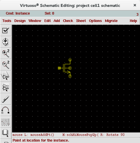
12. Move to schematic window, the status bar will say “point at location for the instance” and you should see the component symbol (yellow) attached to your cursor. Place the device by clicking on the schematic.
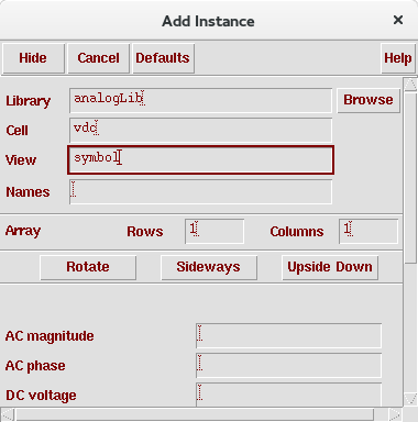
13. Now go back to “Add Instance” window, just type in the library name (“analogLib”) and cell name (“vdc” and “gnd”) for the remaining two components. Place them in the schematic and don’t set any parameters yet.
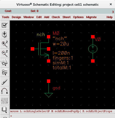
14. After everything is placed, press “ESC” in schematic window to exit “add instance” command.
15. Now connect all the components using "w" or the “wire (narrow)” icon on side-bar. Press “ESC” to exit wire adding mode when done.
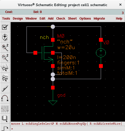
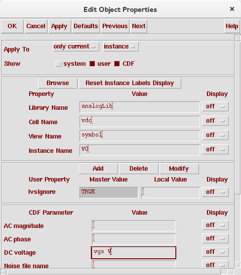
16. Now let’s try editing the voltage source to specify its voltage. Click on the voltage source and press bindkey “q”. “Edit Object Properties” dialog box will show up. Set its DC voltage as “vgs” and click OK.
17. Check and save your schematic with “Shift+X” or “Check and Save” sidebar icon.

MICS IAP Members


