

Running S-parameter Simulation
Authors: Joseph Chong, Jihoon Jeong, Shaver Deyerle, Justin Cartwright, Dr. Dong S. Ha
In this section you will learn how to run S-parameter simulation for the RLC network created.
1. To start simulation, choose Tools->Analog Environment from the top menu, Analog Design Environment (ADE) will appear. Click on Setup-> Simulator/Directory/Host, choose spectre as the "Simulator" and click OK. Then select Variable->Copy from cellview, you will see all the variables defined in schematic show up in "Design Variables" section.
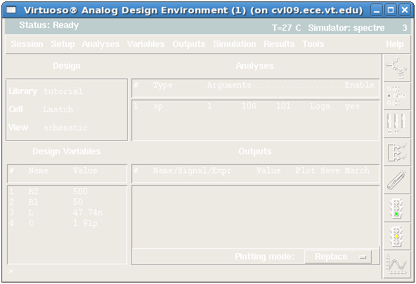
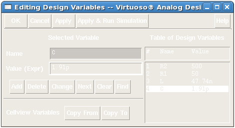
2. Double click each variable and set its value. R2 to 500, R1 to 50, L to 47.74n, and C to 1.91p. Click the Change button after entering each value. Close window when done.
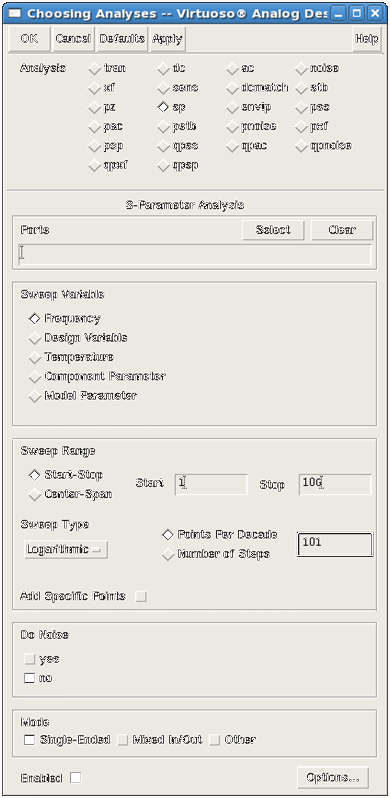
3. Next, from ADE window, select Analysis->Choose or click on the Choose Analyses button on the right toolbar. Choosing Analyses window will appear. This is where you have options to run many different types of analysis from DC to noise simulations. Select the option sp, and more options will appear in the box below.
4. Make sure "Sweep Variable" is Frequency, then set "Sweep Range" from 1 to 10G. (Note: Type 10G for 10 GHz). Select Logarithmic as a "Sweep Type" and give number of "Points Per Decade" (Note: 101 points will be enough). Leave all other settings as is, and click OK.
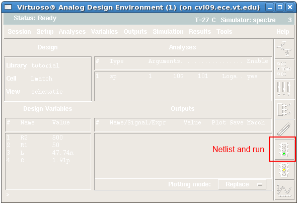
5. Click the "green" traffic signal on the right toolbar of ADE window, Netlist and Run. Output log window will pop up and report simulation progress. In addition, the window will provide debugging information for warnings, errors in the event that errors are present.
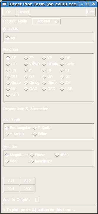
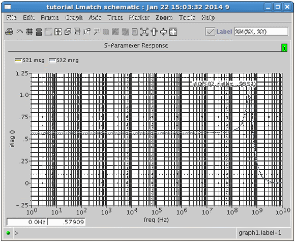
6. In order to plot results, select Results->Direct Plot->Main Form. Direct Plot Form window will appear. Check the SP option under "Function", and select Rectangular "Plot Type" and Magnitude "Modifier". Click S21(Gain) or S12(Reverse Gain) button. The output function will be saved if you activate "Add to Outputs" at the bottom of the window. A Waveform window titled S-Parameter Response shows the selected s-parameter along the desired frequency range. Play with other options. You should be able to see that the maximum gain of the 2-Port Network occurs at 500 MHz as we appropriately add L and C values.

MICS IAP Members


