

Creating Schematics in Cadence
Authors: Joseph Chong, Jihoon Jeong, Shaver Deyerle, Justin Cartwright, Dr. Dong S. Ha
In this section, you will learn how to build a RLC network in Cadence. Let's build a simple L-match transform network which is supposed to transfer the maximum power at a resonant frequency of 500 MHz from source resistance of 50 Ω to load resistance of 500 Ω.
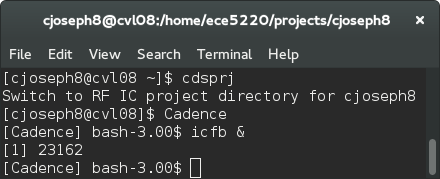
1. If you don't have Cadence Virtuoso (icfb) stated, connect to CVL and run the commands in sequence as: “cdsprj”, “Cadence”, “icfb &”.
2. With Schematic Editing Window activated, hit 'i' key or click on Add->Instance on the top menu. Another way to add instances is to click the chip picture on the left toolbar.
3. An Add Instance window will appear.
4. Click the "Browse" button, a Library Browser window will pop up. Select analogLib library from top-down lists, add an inductor(ind), and a capacitor(cap) by clicking instances in Component Browser window and placing your cursor on the Schematic Editing window. Make sure that you clicked "View Name" of symbol for instances.
Note: In this tutorial, we will use ideal passive components from analogLib library for an educational purpose.
5. While placing instances on the Schematic Editing, replace a value of "Inductance" to 'L' shown in figure. Repeat the same procedure for the capacitor(the capacitance value 'C') respectively. Hit 'ESC' to escape from any previous action.
Note: If you want to change a property of a component at any time, click the component and hit 'q'. Edit Object Property window will show up and you will be able to modify any value of the object.
6. To analyze a parallel RLC network, add ports and a ground into your schematic. The port can be found in analogLib->Port. The ground component is available in analogLib->gnd. When placing these port sources, you should set resistance value and fill in port number. For PORT0 on the left, set resistance as R1, and port number as 1. For PORT1 on the right, set resistance as R2, and port number as 2. Refer to the graph in step 7.
Note: The instance name 'PORT0' and 'PORT1' is irrelevant. Port number is used in simulation instead.
7. In order to connect those components in your schematic, hit 'w' and wire those. Alternative ways to initiate wiring are Add->Wire from the top menu or click the wire picture from the left toolbar. Click check and save when done.

MICS IAP Members


