

Post-layout Simulation for an Amplifier
Authors: Joseph Chong, Ji Hoon Hyun, and Dr. Dong S. Ha
In this section you will learn how to perform post-layout simulation with the av_extracted view and the testbench we created in previous tutorials.
Note: You may want to check the file /software/PDK/65nm_TSMC_RF/PDK_doc/RF_flow/N65_PDK_rf_flow_guide_v1d0.pdf in CVL for more information.
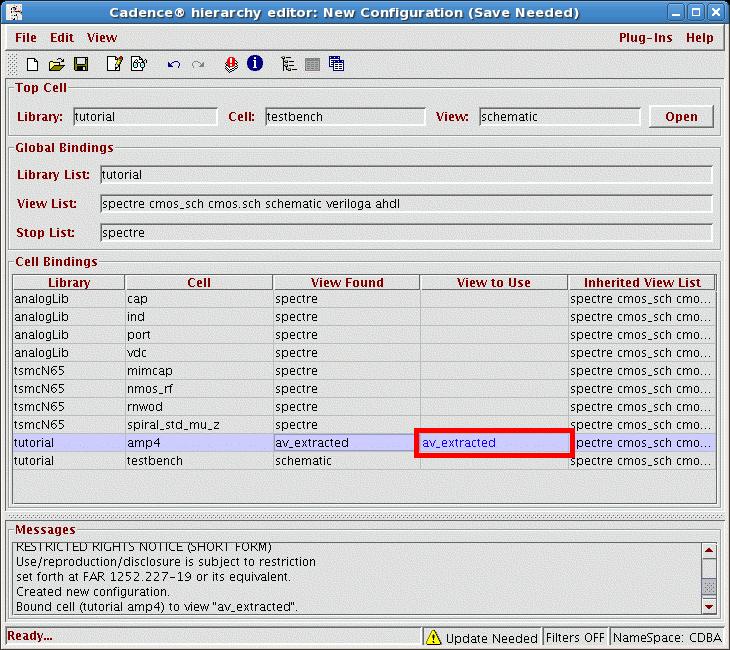
1. In the icfb window or the Library Manager, create a new cellview for testbench. Set View Name as config, and make sure the Tool is Hierarchy-Editor.
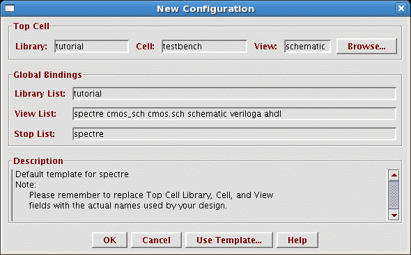
2. A New Configuration form will pop out. At the top the form enter the View to schematic, and at the bottom, click on the Use Template.... The Use Template form opens; cycle the Name to spectre and click OK. Change the Library List to the name of your current library. Then the New Configuration form is as shown below.
3. Click OK. Now we're going to change the original amplifier in our testbench to the newly extracted layout. Find the amplifier in the list (e.g. amp4), and enter av_extracted as the View to Use.

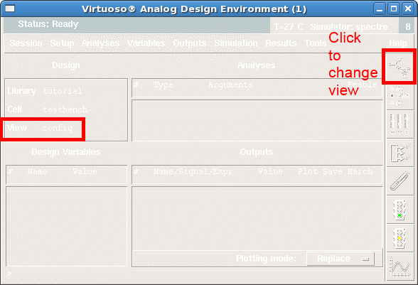
4. Now start an Analog Design Environment, change the View to config and run simulation.
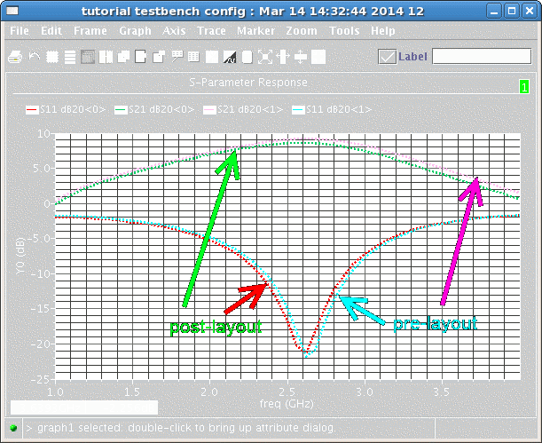
5. You can now compare your pre-layout and post-layout simulation results.

MICS IAP Members


