

Post Layout Process for an Amplifier
Authors: Joseph Chong, Ji Hoon Hyun, and Dr. Dong S. Ha
In this section you will learn how to perform physical verification for the layout an amplifier. Physical verification includes Design Rule Check (DRC), layout VS schematic check (LVS), and parasitic extraction (RCX) for post-layout simulation. In this tutorial, we will perform DRC with Mentor Graphics Calibre, and perform LVS & RCX using Assura for our TSMC 65nm design.
DRC will check to make sure that the layout you have made is possible to fabricate according to the foundry rules. LVS checks that our layout (components/connections) is correctly setup compared to the schematic. RCX extracts parasitic resistance and capacitance from layout interconnects to include in simulation for a more realistic result. It is recommended to run DRC during the process of layout to make sure your metal width / spacing are according to the rules. Run LVS after layout is completed. RCX needs a prior completed LVS.
Note: This guide is for running DRC/LVS/RCX for TSMC 65nm technology only, and most of the information below comes from the design manual. If you’re working on other technologies, you will need to check relevant design manual.
Environment Setup
1. In order to run Calibre from Cadence layout window, an initiation file needs to be included at Cadence startup. Copy the file to your project startup directory with the command below or create one.
| Terminal Code (case sensitive): cp /home/ece5220/.cdsinit . |
2. The environment setup has copied the cds.lib which contains avTech to your project folder. Now, copy the file assura_tech.lib and the folder Assura from technology process design kit (PDK) directory to your project directory.
| Terminal Code (case sensitive): |
| cp -r /home/ece5220/PDK/65nm_TSMC/{Assura,assura_tech.lib} . |
Running Design Rule Check (DRC)
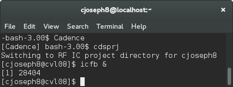
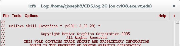
1. The OS version on CVL is not compatible with current Mentor Graphics installation. Therefore we will override the parameters by starting Cadence with a DIFFERENT SEQUENCE: “Cadence”, “cdsprj”, and “icfb &”, so that we can run an old version of Calibre. Make sure you have Calibre Skill Interface message in icfb window.
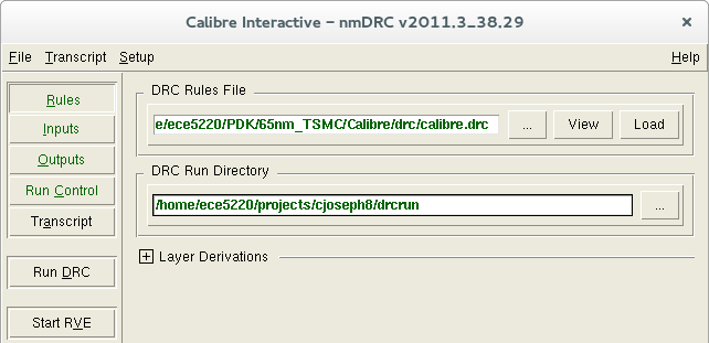
2. In the layout window, go to Calibre → Run DRC. If you have already created the runset, load the runset and skip to Step 5. Otherwise, close the "Load Runset File" form. In the interactive window, select the Rules tab and type (or copy and paste) the following text into the DRC Rules File box. Then, select Load.
| DRC Rules File |
| /home/ece5220/PDK/65nm_TSMC/Calibre/calibre.drc |
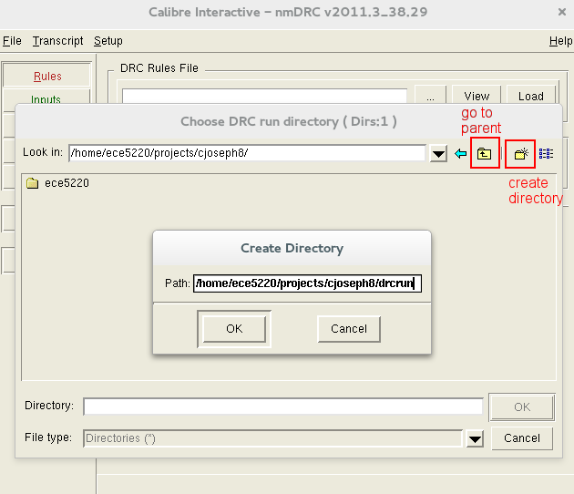
3. We will make a directory for the drc information to be stored. Click on the “…” button, then click on “create directory” button at top-right corner, and add /drcrun to your current project directory. Click OK, click “go to parent directory”, then select drcrun folder and click OK. Changing your DRC run directory to this location so you don't flood your project space with drc files.
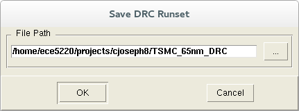
4. Let's save this runset. Go to File → Save Runset. With the File Path empty, press OK. In the next window, give it a name (e.g. TSMC_65nm_DRC). Click OK twice to save. You can load this runset by selecting it next time you start Calibre.
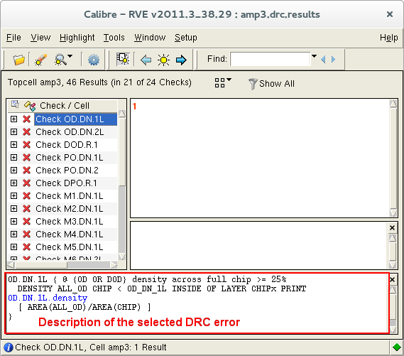
5. Click on the Inputs tab and verify that the file information is correct, then select Run DRC. Once it is complete (which may take a while, even on campus), a summary file and the Results Viewing Environment (RVE) window will appear. The bottom panel of RVE shows description of the error and may give a hint on how to fix it. Basically you need to fix all of the errors before submitting layout for fabrication. But you don’t need to do that in the context of ECE5220 class project. Find out which error should be fixed, and how to fix them in How to Solve DRC Errors page. You may proceed to run LVS without fixing the errors.
Running the Layout versus Schematic (LVS) Check
1. Open the layout we created. Make sure that Assura is on the menu of layout editor window.
2. Click Assura->Run LVS... in layout window to invoke Run Assura LVS graphic user interface.
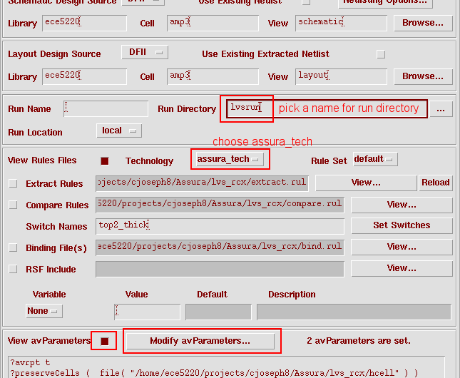
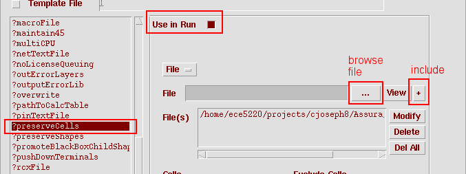
3. In Run Assura LVS window, fill in Run Directory with any name and select assura_tech in the Technology scroll down menu. Enable the View avParameters button, the click on Modify avParameters button. In the popup LVS avParameters window, scroll down and select ?preserveCells on the list. Enable the Use in Run button, use the “…” button to browse for the hcell file, the use the “+” button to include the file. If you don’t have the files, repeat Step 2 in Environment Setup section above.
4. Click OK to run the Assura LVS and see the result. If the layout isn't matched to schematic, check How to Solve LVS Errors page on how to fix them. You have to manually re-edit the layout and re-run the LVS check to make the LVS result matched. A matched result is shown as below.
Running Parasitic RC Extraction (RCX)
1. You may NOT proceed unless you have solved all LVS errors.
2. From the layout editor window, click Assura->Run RCX... to invoke Assura RCX graphic user interface.
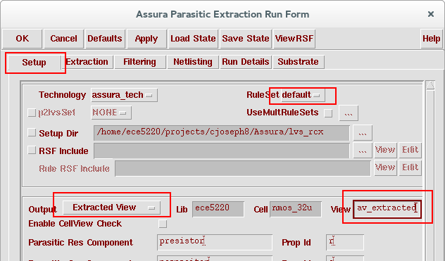
3. Select Output to Extracted View in Setup tab of Assura RCX window to output extract result to av_extracted view.
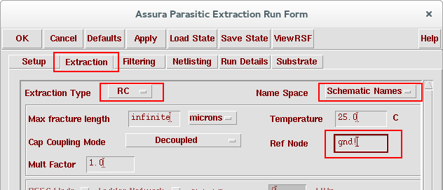
4. In the Extraction tab of Assura RCX window, select the extraction mode to RC, set the Name space to Schematic Names and fill in the Ref Node (here we use gnd!).
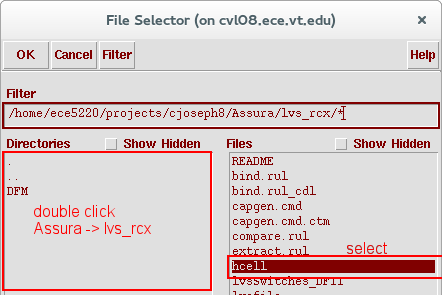
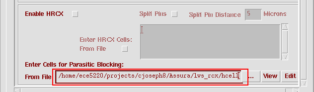
5. Enter hcell file in Assura/lvs_rcx/ folder for Parasitic Blocking.
6. Click OK to start the Assura RC extraction. After the RC extraction is completed, a new view (av_extracted view) which contains not only the original components but also the parasitic devices will be generated and then can be used for post-layout simulation.

MICS IAP Members


