

Back End Design Using Cadence Tool – Physical Implementation
Authors: Hetaswi Vankani, Adithya Venkatramanan, and Dr. Dong S. Ha
Tool: Encounter Digital Implementation (encounter)
Add stripes
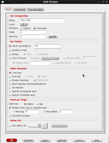
1. Power → Power Planning → Add Stripe
2. Parameter values:
a. Nets: VDD, VSS
b. Layer: AP
c. Width: 3 Spacing: 5
d. Set-to-set distance: 20
e. Y from top: 5 Y from bottom: 5
3. Hit Apply
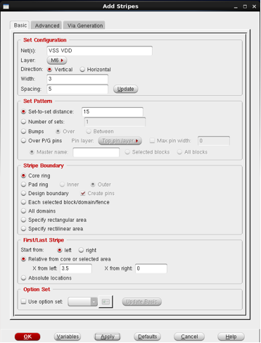
4. Power → Power Planning → Add Stripe
5. Parameter values:
a. Nets: VDD, VSS
b. Layer: M6
c. Width: 3 Spacing: 5
d. Set-to-set distance: 15
e. X from left: 3.5
f. Hit OK
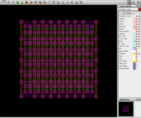
6. After hitting OK the design appears as shown in fig 13.
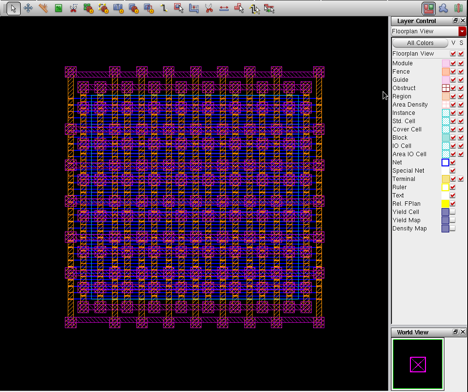
7. Special Route
a. Route → Special Route
b. Hit OK
Special routes as in fig 14 are created.

MICS IAP Members


