

Front End Design Using Synopsys Tool – Part 02 (dc_shell)
Author: Hetaswi Vankani, Adithya Venkatramanan, Dr. Dong S. Ha
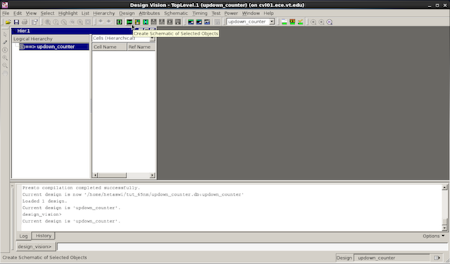
5. Create Schematic: Select the design in logical hierarchy window and select the second symbol in the GUI panel as shown in the picture below to create schematic.
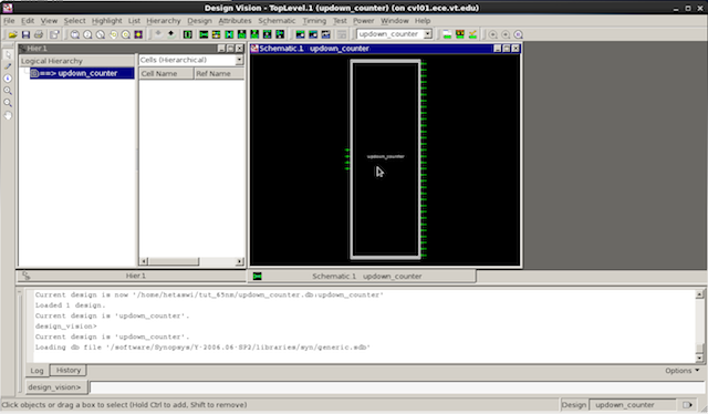
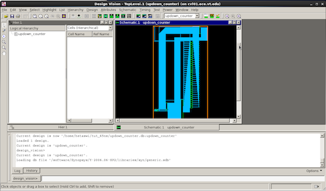
6. If you double click on the symbol below you will be able to see the logic interconnect.

MICS IAP Members


